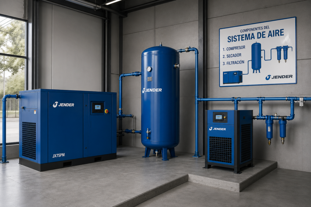
A screw air compressor consists of a set of interconnected components: the air-end compresses air using two helical rotors, the inlet filter protects this process, the separator removes oil from the compressed air, the cooling system controls the temperature, and the control panel coordinates the entire cycle. Understanding what each part does allows for problem detection before production stops.
In this article, you will see the main parts of a screw compressor, their respective functions, and what signals indicate an impending failure. If you are evaluating which equipment to install, Jender’s range of industrial screw compressors covers models from fixed speed to units with variable frequency drives and integrated dryers.
What distinguishes the screw compressor from other types?
The screw compressor generates compressed air continuously, without on-off cycles like piston compressors. Two helical rotors (male and female) rotate in opposite directions within a sealed chamber: air is trapped between the lobes, the available volume decreases, and pressure progressively rises without pulsations. This principle makes it the go-to equipment for industrial environments with constant air demand.
The absence of reed valves and reciprocating motion reduces mechanical wear and allows for stable working pressures between 7 and 13 bar in most industrial applications.
The Air-End: Where Compression Occurs
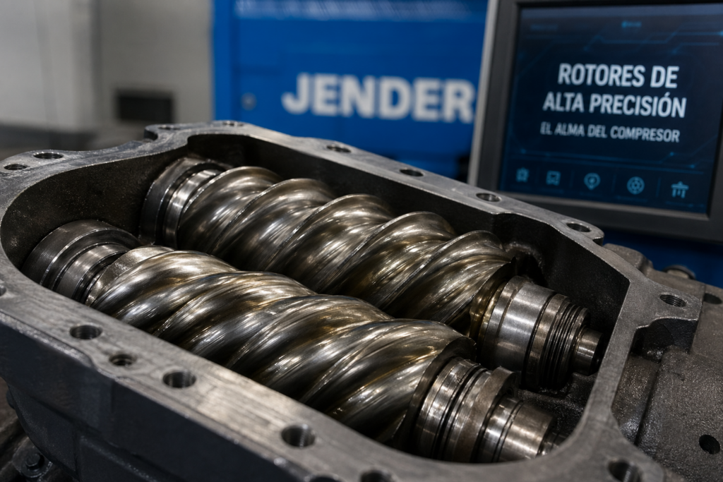
The air-end, also called the compressor unit or compressor block, is the core part of the equipment. Inside are the two rotors, the housing that contains them, the bearings that support them, and the seals that prevent leaks.
- Male and female rotors: The male rotor has fewer lobes (generally 4) and acts as the driver; the female has more (generally 6) and is driven by the male. Their precision grinding directly determines the compressor’s efficiency: micron-level tolerances between the two rotors prevent internal leaks without requiring contact.
- Housing: Encloses the rotors and directs the flow of air and oil. Made of cast iron, it withstands internal pressures and absorbs some of the heat generated during compression.
- Bearings: Both radial and axial, they support the rotors and ensure they rotate with correct alignment. They are a scheduled wear part: as they approach the end of their service life, they increase equipment vibration and noise.
- Shaft seals: Prevent lubricating oil from contaminating the compressed air and air from escaping to the outside. A deteriorated seal is detected by the presence of oil in the line or by an unexplained pressure drop.
Inlet Air Filter
It is located before the intake valve, and its job is to retain dust particles, dirt, and contaminants before they enter the air-end. A multi-layer filter can capture particles down to 1 µm. When saturated, the airflow into the compressor is reduced, and the equipment needs to work harder to reach the set pressure, resulting in higher power consumption and a higher discharge temperature.
The clearest sign that the filter is at its limit is the differential pressure gauge: when the pressure difference between the filter’s inlet and outlet exceeds the manufacturer’s threshold, it must be replaced. In dusty environments or those with metal shavings, this interval can be reduced to half the standard.
Intake Valve and Load Modulation
The intake valve controls the air entry into the air-end. When the compressor operates at full load, the valve is fully open; when demand drops or maximum pressure is reached, it partially or fully closes, allowing the unit to idle without stopping the motor.
In compressors with variable frequency drives, this modulation is managed by the drive adjusting the motor speed, which eliminates the energy losses associated with idling. This is one of the strongest technical arguments for choosing an inverter-equipped unit in installations with variable demand.
Electric Motor and Transmission System
The motor converts electrical energy into rotational motion to drive the air-end. Modern equipment uses IE3 or IE4 motors (high energy efficiency) with permanent magnets in some variable speed ranges.
The transmission between the motor and the air-end can be direct (direct coupling, no belts) or via a V-belt. Direct coupling eliminates frictional losses from the belt and reduces maintenance, although its initial cost is higher. In belt drives, incorrect tension is a frequent cause of premature wear of bearings in the air-end.
Lubrication System: Oil and Its Circuits
In oil-lubricated screw compressors, the lubricant performs three functions simultaneously: it seals the space between rotors to prevent internal leaks, lubricates bearings and moving parts, and absorbs the heat generated during compression. Therefore, the quality and condition of the oil directly affect the equipment’s performance.
The oil circuit includes the oil pump (in some models, differential pressure moves the oil without an additional pump), the oil filter, which retains metallic particles and contaminants from the lubricant, and the oil cooler, which lowers the lubricant’s temperature before reintroducing it into the cycle.
Degraded oil increases internal friction, raises the discharge temperature, and accelerates the wear of bearings and seals. Periodic replacement, generally every 2,000 operating hours or at least once a year, is the maintenance intervention with the greatest impact on the equipment’s service life.
Oil-Air Separator
After compression, the air reaches the separator tank laden with suspended oil droplets. The separator retains them using a nanofiber cartridge that causes coalescence: micro-droplets combine, fall by gravity, and the recovered oil returns to the lubrication circuit. A separator in good condition keeps oil carryover in the compressed air below 2-5 ppm.
When the separator is saturated, the pressure drop it generates forces the compressor to work harder to reach the set pressure. This is detected by measuring the pressure difference before and after the separator: if it exceeds the manufacturer’s specified value, the cartridge must be replaced.
Cooling System
Compression generates heat. Without an efficient cooling system, the air discharge temperature can exceed 80-90 °C, which degrades the oil, deteriorates the seals, and can trigger an over-temperature shutdown.
The cooling system includes the oil cooler and the air aftercooler, which lowers the temperature of the compressed air before it leaves the unit. In most industrial compressors, cooling is air-based, with a fan driven by the same motor or an independent one. In installations with high ambient thermal load (compressor rooms above 40 °C), forced ventilation or water-cooled systems are common.
Control Panel
The electronic controller is the compressor’s brain. It monitors working pressure, discharge temperature, operating hours, filter status, and active alarms in real-time. In modern equipment, it also manages loading and unloading, variable frequency drive speed, and communication with plant control systems (Modbus, Profibus, IO-Link).
A screen with an alarm history is the primary diagnostic tool before calling technical service. Most unscheduled shutdowns leave a record that helps identify whether the cause was over-temperature, an oil pressure drop, or a voltage failure.
Most Common Component Failure Signs
Knowing the parts is only useful if you know what symptom each failure produces. This table lists the most frequent ones in industrial environments:
| Component | Typical Failure Sign |
|---|---|
| Saturated air filter | High power consumption, high discharge temperature |
| Degraded oil / clogged oil filter | Over-temperature, increased consumption, accelerated wear |
| Deteriorated oil-air separator | Oil carryover in the line, abnormally high oil consumption |
| Worn air-end bearings | Unusual noise or vibration, high bearing temperature |
| Intake valve issues | Compressor does not reach set pressure, or does not unload correctly |
| Clogged cooler | Over-temperature shutdown, especially in summer |
| Loose or worn drive belt | Loss of flow, air-end bearing overheating |
Preventive maintenance starts with knowing your equipment
A compressor stopped in production is not just a technical problem: in an industrial line, it can cost more in downtime hours than an entire year’s maintenance. That’s why Jender screw compressors are designed with direct access to the most common maintenance points, long-life filters, and top-tier components. Jender’s technical service operates 24 hours a day, 365 days a year, with response times that minimize downtime.
If you need to assess which equipment best suits your installation’s needs, you can consult Jender’s complete range of industrial screw compressors, with models from fixed speed to direct variable frequency drive and integrated dryer.
